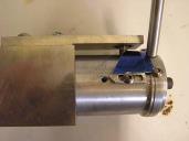
is wrapped around the mold at a given
radius. A fixture can be made to hold
both this pitch template and the
propeller.
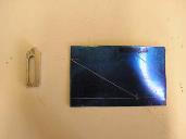
The pitch template is designed to take
up around 1/4 of the pitch drum’s two
inch diameter, so for our ABC 2018 prop
we need to layout a line 1/4 of the pitch
drum’s circumference long. That is .25 x
2 x 3.1416 = 1.57 inches long. At right
angles to this we need a line 1/4 the pitch
long or 1/4 x 3.6 = .9 inches long. The
triangle formed by this layout gives an
unwrapped picture of the pitch at two
inches diameter.
PROPWASH
6
April 2014
Props Part 2 – Geometry
(Continued from page 5)
and could be compared to the disk area of the propeller. Most model propellers have
around 50% projected blade area to disk area for two blade props and around 75% for
three blade props. A way to generate this arc will be discussed next.
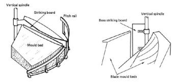
So how are propellers actually made? Long before there were computers, the
principles outlined above and in Part 1 were used to generate propeller shapes. A
foundry sand base was shaped by rotating a striking board around the propeller axis.
This board was angled to give the desired rake and followed a pitch rail set at a fixed
radius. The hub was swept in the sand with a similar method. This gives the shape of
the hub and rear (stern facing) side of the prop.
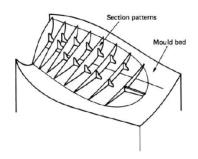
The blade form was laid out on
each mold bed with templates and
filled with a sand mix. A reinforced
mold was formed over this for each
blade. The upper mold was then
lifted and the template structure and
sand was cleared. A core for the
shaft bore was added and final hand
shaping was done. Finally, runners
were added to feed metal to the hub.
After casting the propellers, they
were smoothed by hand and the shaft
bore was finished. Today large, one
off propellers can still be made with
similar methods but are often
finished with multi axis CNC
machines. If more than one propeller
is needed, a conventional wood
pattern might be made. A
streamlined version of these methods
can be used to machine model
propellers.
Understanding how this works
helps understand propeller geometry.
Of course one off propellers can also
be cast with sand or lost wax tech-
niques just like large propellers.
The first thing to realize is that
for constant pitch, the pitch rail
described above is a straight line that
Graphics of how sand casted props were made before there were computers
Blade templates in the upper mold after removal
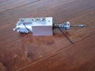
A pitch cutting fixture
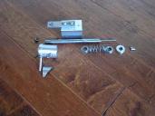
Pitch cutting fixture - exploded view
Pitch template layout and cup bracket
Pitch template and cup bracket installed
on Pitch Drum