
cut the blade outline. More than one
radius can be cut and blended together if
necessary.
The propellers made by these fixtures
will need some hand finishing,
especially sharpening the leading edge.
A variety of materials can be cut ranging
from machinable wax to steel. The
advantage of this or fancier digital
propeller manufacturing is the ability to
explore the effects of exact changes in
propeller geometry. Making a propeller
with these methods is a lot of work. 3D
printing and casting for one off props is
expensive. Most of the time, a stock
casting can be made to work very well.
In the final part on propellers ,we will
look at how to improve and modify
existing stock propellers.
Editors note: Lohring Miller is
currently our NAMBA Safety Chairman.
He was inducted in to the NAMBA Hall
of Fame in 2011. He has been a past
District Eight Director several terms and
Contest Director of two NAMBA
Nationals. Lohring not only contributes
safety articles for the Propwash, he also
provides tech articles on a continuing
basis. Please refer to past issues of the
Propwash online if you may have missed
some of his writings.
PROPWASH
April 2014
7
Bending this to fit the pitch drum allows a constant pitch propeller to be machined.
This template could also be formed to give progressive pitch. In that case the pitch line
would be a concave curve with a power angle at the short end blended to a higher
angle at the trailing edge. The cup is set by adjusting the bracket that holds the tall side
of the pitch template. Several brackets with various angles can be made. The basic
characteristic will be a set cup height as described above. A 1/8 inch radius transition
is set by the 1/4 inch diameter template follower. This is matched in the blade by a 1/4
inch end mill. Rake is set by angling the fixture in the milling machine. In this case we
matched the ABC 2018’s 10 degree rake.
An indexing feature allows rotating the pitch drum relative to the shaft to cut
multiple identical blades. The drum can also be rotated two different small fixed
amounts with two offset holes to give a tapered blade cross section. The ball end mill
gives a blade to hub radius. A video of a similar fixture used to cut helical gears can be
found at http://www.youtube.com/watch?v=blaZ5tz0_6E.
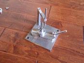
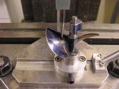
The blade outline can be machined in a second fixture. The propeller is mounted on
a shaft on a rotary base. The base rotates around a central axis marked by the shaft
hanging from the arm. The propeller shaft assembly is moved along the slide to locate
the center of the radius from the propeller
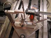
shaft centerline. The two screws on the
shaft assembly lock it to the rotary base to
hold this. The propeller is rotated to locate
the center of the radius relative to the
trailing edge. The upper screw on the
propeller shaft assembly locks the blade in
position, and the lower screw indexes the
other blades into the same position. The
fixture is located in the milling machine
from the central axis shaft to determine the
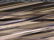
radius. See the full propeller picture to get
an idea of how a radius in one plane can
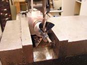
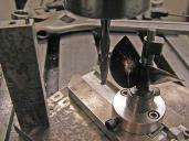
The fixture in the milling machine
The index disk showing the offset holes
The propeller in the fixture
Blade Outline Fixture
Setting Blade Radius Location from Shaft
Center
The blade radius center location
Milling the blade outline