
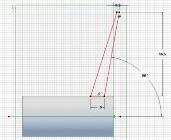
The shape in this case is thicker at the
hub and is raked (explained later) 20
degrees.
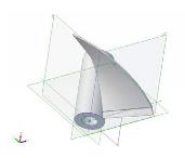
We revolve and advance this cross
section forward at the basic pitch to
create most of the blade surface and
rearward at a higher pitch to create the
cupped section. The pitches can be
constant or varying as the shape revolves
along the axis. A varying pitch is often
called progressive pitch and may be
described as progression percent.
Cup can be measured several ways.
In the above example we used an
increased pitch for a small distance. That
is very similar to a method suggested by
HydroComp. Cup is used to increase the
effective pitch of the prop. They found
in full sized props that this increase was
around 21 times the height of the cupped
section. That is, a 250 mm diameter prop
with a 1.85 mm cup had an increase in
effective pitch of around 39 mm. They
suggest using a cup gauge with various
steps like the ones pictured on page 5.
We effectively measure cup in a similar
way with our pitch gauges as explained
in the following.
PROPWASH
4
April 2014
In Memory of Wreno Wynne
By Wes Wynne
North Texas Battle Group
My father was a rare individual who
could brighten anyone’s day. He will
be dearly missed by many.
Model warship combat attracts
different people for different reasons.
Some enjoy the strategy of combat,
others appreciate the history, some like
the technical challenges, and some just
get a kick out of shooting things to bits.
For my dad, the hobby was about the
close friendships he developed all over
the world. He loved helping others
with the various technical and
engineering problems they
encountered. More to the point, he
spent more time helping others with
their challenges than working on his own ships. His enjoyment came from the close
camaraderie with others. As many have said, Combat will never be the same without
him.
Editors Note: Wreno Wynne was the NAMBA Combat Chairman from 2008 until
his recent passing. He was most known for being a member of the North Texas Battle
Group in District Seven and coordinating the annual North American Big Gun Open
Championships in Kaufman, Texas.
Props Part 2 – Geometry
By Lohring Miller
NAMBA Safety Chairman
Now that we’ve covered some of the basic propeller theory, let’s look at an actual
prop. There are two ways to visualize how a propeller works. Starting with the Wright
brothers, aerodynamic engineers have thought of a propeller as a rotating wing. We
looked at the blade sections in the October 2013
Propwash
Part 1 this way. Long
before this, marine engineers thought of a propeller as a screw advancing through
water in the same way as a screw advances through a solid object. We are going to use
this system to explore propeller geometry.
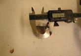
By far the most important dimension of a propeller is its diameter. Remember from
Part 1, that the power absorbed varies as the fifth power of the diameter. Very small
changes in diameter result in big changes in the power needed to turn a given rpm.
Fortunately, diameter is easy to understand and measure. A three blade propeller, or
individual blades of any propeller, can be measured by measuring from the blade tip
over a shaft through the center. Subtract one half the shaft diameter and you have the
blade radius.
The next feature of a propeller we need to
measure is the pitch. A propeller’s pitch is
the same as a screw’s. It is the distance a
screw advances through a solid in one
revolution. Our propellers are usually made
with constant pitch from the edge to the hub.
However, because the circumference is
smaller at the hub than at the tip, the blade
angle at the hub will be greater. You can
visualize this as a shape revolved and
advanced around an axis like that in the
pictures in the next column.
Propeller Blade Radius Measurement
A propeller blade cross section
Cross Section Rotated and Advanced
Along an Axis